The term wireless communication was
introduced in the 19th century and wireless communication technology has
developed over the subsequent years. It is one of the most important
mediums of transmission of information from one device to other devices.
In this technology, the information can be transmitted through the air
without requiring any cable or wires or other electronic conductors, by
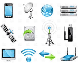
using electromagnetic waves like IR, RF, satellite, etc. In the present
days, the wireless communication technology refers to a variety of
wireless communication devices and technologies ranging from smart
phones to computers, tabs, laptops, Bluetooth Technology, printers. This article gives an overview of wireless communication and types of wireless communications.
Types of Wireless Communciation
Introduction To Wireless Communication
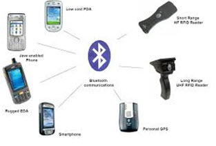
In
the present days, wireless communication system has become an essential
part of various types of wireless communication devices, that permits
user to communicate even from remote operated areas. There are many
devices used for wireless communication like mobiles. Cordless
telephones, Zigbee wirelss technology,
GPS, Wi-Fi, satellite television and wireless computer parts. Current
wireless phones include 3 and 4G networks, Bluetooth and Wi-Fi
technologies.
Types of Wireless Communication
The
different types of wireless communication mainly include, IR wireless
communication, satellite communication, broadcast radio, Microwave
radio, Bluetooth, Zigbee etc.
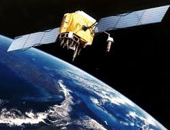
Satellite Communication
Satellite
communication is one type of self contained wireless communication
technology, it is widely spread all over the world to allow users to
stay connected almost anywhere on the earth. When the signal (a beam of
modulated microwave) is sent near the satellite then, satellite
amplifies the signal and sent it back to the antenna receiver which is
located on the surface of the earth. Satellite communication contains
two main components like the space segment and the ground segment.The
ground segment consists of fixed or mobile transmission, reception and
ancillary equipment and the space segment, which mainly is the
satellite itself.
Satellite Communciaiton
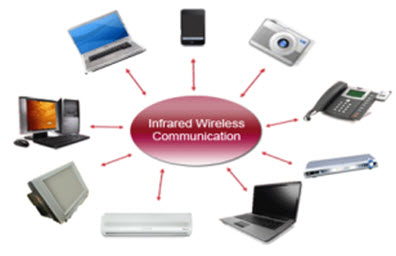
Infrared Communication
Infrared wireless communication communicates
information in a device or systems through IR radiation . IR is
electromagnetic energy at a wavelength that is longer than that of red
light. It is used for security control, TV remote control and short
range communications. In the electromagnetic spectrum, IR radiation lies
between microwaves and visible light. So, they can be used as a source
of communication
Infrared Communication
For
a successful infrared communication, a photo LED transmitter and a
photo diode receptor are required. The LED transmitter transmits the IR
signal in the form of non visible light, that is captured and saved by
the photoreceptor. So the information between the source and the target
is transferred in this way. The source and destination can be mobile
phones, TVs, security systems, laptops etc supports wireless
communication.
Broadcast Radio
The
first wireless communication technology is the open radio communication
to seek out widespread use, and it still serves a purpose nowadays.
Handy multichannel radios permit a user to speak over short distances,
whereas citizen’s band and maritime radios offer communication services
for sailors. Ham radio enthusiasts share data and function emergency
communication aids throughout disasters with their powerful broadcasting
gear, and can even communicate digital information over the radio
frequency spectrum.
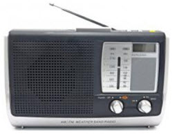
Broadcast Radio
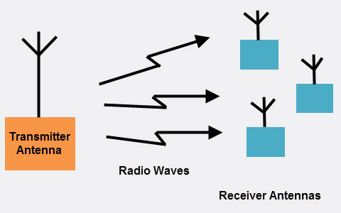
Mostly
an audio broadcasting service, radio broadcasts sound through the air
as radio waves. Radio uses a transmitter which is used to transmit the
data in the form of radio waves to a receiving antenna(Different Types of Antennas).
To broadcast common programming, stations are associated with the
radio N/W’s. The broadcast happens either in simulcast or syndication or
both. Radio broadcasting may be done via cable FM, the net and
satellites. A broadcast sends information over long distances at up to
two megabits/Sec (AM/FM Radio).
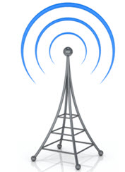
Radio
waves are electromagnetic signals, that are transmitted by an
antenna.These waves have completely different frequency segments, and
you will be ready to obtain an audio signal by changing into a frequency
segment.
Radio
For
example, you can take a radio station. When the RJ says you are
listening to 92.7 BIG FM, what he really means is that signals are being
broadcasted at a frequency of 92.7megahertz, that successively means
the transmitter at the station is periodic at a frequency of 92.700,000
Cycles/second.
When you would like to
listen to 92.7 BIG FM, all you have to do is tune the radio to just
accept that specific frequency and you will receive perfect audio
reception.
Microwave Communication
Microwave wireless communication
is an effective type of communication, mainly this transmission uses
radio waves, and the wavelengths of radio waves are measured in
centimeters. In this communication, the data or information can be
transfers using two methods. One is satellite method and another one is
terrestrial method.
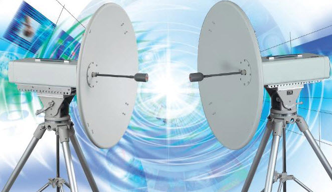
Microwave Communication
Wherein
satellite method, the data can be transmitted though a satellite, that
orbit 22,300 miles above the earth. Stations on the earth send and
receive data signals from the satellite with a frequency ranging from
11GHz-14GHz and with a transmission speed of 1Mbps to 10Mbps. In
terrestrial method, in which two microwave towers with a clear line of
sight between them are used, ensuring no obstacles to disrupt the line
of sight. So it is used often for the purpose of privacy. The frequency
range of the terrestrial system is typically 4GHz-6GHz and with a
transmission speed is usually 1Mbps to 10Mbps.
The main disadvantage of microwave signals is, they can be affected by bad weather, especially rain.
Wi-Fi
Wi-Fi is a low power wireless communication,
that is used by various electronic devices like smart phones, laptops,
etc.In this setup, a router works as a communication hub wirelessly.
These networks allow users to connect only within close proximity to a
router. WiFi is very common in networking applications which affords
portability wirelessly. These networks need to be protected with
passwords for the purpose of security, otherwise it will access by
others
Wi-Fi Communication
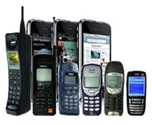
Mobile Communication Systems
The
advancement of mobile networks is enumerated by generations. Many
users communicate across a single frequency band through mobile phones.
Cellular and cordless phones are two examples of devices which make use
of wireless signals. Typically, cell phones have a larger range of
networks to provide a coverage.But, Cordless phones have a limited
range. Similar to GPS devices, some phones make use of signals from
satellites to communicate.
Mobile Communication Systems
Bluetooth Technology
The
main function of the Bluetooth technology is that permits you to
connect a various electronic devices wirelessly to a system for the
transferring of data.Cell phones are connected to hands free earphones,
mouse, wireless keyboard. By using Bluetooth device the information from
one device to another device. This technology has various functions and
it is used commonly in the wireless communication market.
Bluetooth Technology
Advantages of Wireless Communication
Any data or information can be transmitted faster and with a high speed
Maintenance and installation is less cost for these networks.
The internet can be accessed from anywhere wirelessly
It is very helpful for workers, doctors working in remote areas as they can be in touch with medical centers.
Disadvantages of Wireless Communication
An unauthorized person can easily capture the wireless signals which spread through the air.
It is very important to secure the wireless network so that the information cannot be misused by unauthorized users
Applications of Wireless Communication
Applications of wireless communication involve security systems, television remote control, Wi-Fi, Cell phones, wireless power transfer, computer interface devices and various wireless communication based projects.
Wireless Communication Based Projects
Wireless communication based projects mainly include different technologies like Bluetooth, GPS, GSM, RFID and Zigbee projects which are listed below.
Wireless Communication Based Projects
Android Based Smart Phone Used for Induction Motor Control
Therefore,
this is all about Types of wireless communication, these networks are
one of the important technologies in the telecommunications market.
WiFi, WiMax, Bluetooth, Femtocell, 3G and 4G are some of the most
important standards of Wireless technology The information which is
given in this article will be helpful to the viewers.Furthermore, any
queries, suggestions or electronics projects,
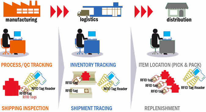
Radio frequency is an automatic
identification process used for transmitting data between an RFID tag
and RFID reader with the help of radio-frequency electromagnetic fields.
The RFID tag is a device used to store data of any stuff, persons,
books, animals, etc. RFID tags
are of different types some tags can be placed near to the RFID reader
and some can read from far away distances beyond the line of sight of
the reader.
RFID Applications
There are different types of RFID systems
in the market that consists of an antenna, transceiver and a
transponder. These systems operate at different frequency ranges like
low frequency (30-500 kHz), mid frequency (900-1500 kHz) and high
frequency (2.4-2.5GHz). Let us see one of the example based application
of RFID-based-attendance-management system in brief.
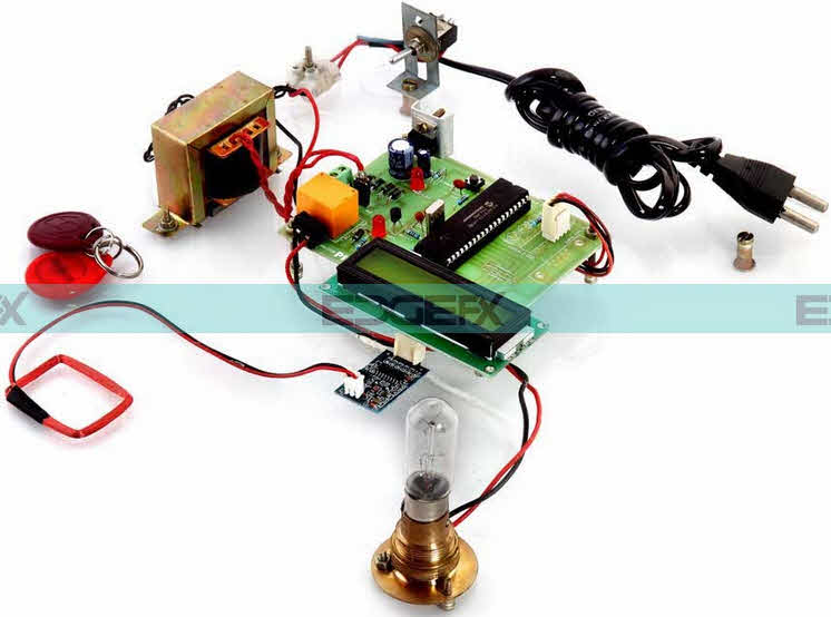
RFID Based Attendance System
The
aim of this project is to maintain the record of the students’
attendance by using RFID tags. Each student is issued with his/ her
authorized tag, which can be used for swiping in front of the RFID
reader to record their attendance.
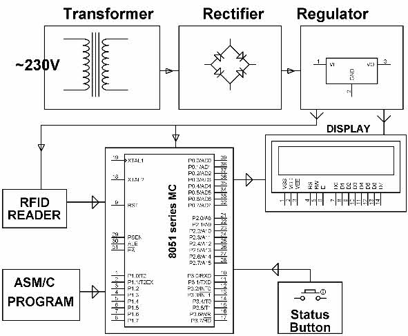
Block Diagram of RFID based Attendance System by Edgefxkits.com
In
most of the colleges and schools,attendance is recorded manually – such
a process consumes lots of time. In this proposed system, attendance
system is implemented by using advanced wireless technology
“RFID”. Only the authorized students are provided with the RFID tags.
This tag consists of an inbuilt integrated circuit for storing and
processing information.
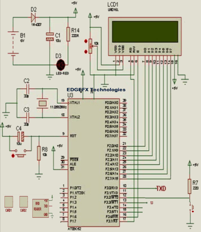
Oscillator circuit is connected between the 18 and 19 th pin of the microcontroller and consist of an oscillator with a frequency of 11.0592 MHz and two capacitors of 33pF.
Preset Circuit
The 9th pin of the microcontroller is RST pin, which is reset pin. This preset circuit comprises a switch, a capacitor of (10u) and a resistor of 10k. When the switch is pressed, the RST pin is connected to the power supply(Vcc) and the microcontroller gets reset.
Circuit Diagram of RFID based Attendance System
LCD Display
The LCD display
is used for displaying the data. It consists of 16 pins: three pins are
connected to the power supply, and the remaining pins are connected to
the port 2 of the microcontroller.
RFID Reader
The RFID reader is a module with RFID reader and antenna. It is small in size and integrates with any sort of hardware design. It is used to read the data stored in the RFID tags.
Circuit Working
The
data stored in this tag is referred to as the identification and
attendance of the person. Once the student places the card in front of
the RFID reader, it reads the data and compares the data stored in the microcontroller which is programmed by using Embedded C language.
If the data matches, then it displays the information on the LCD. This
RFID attendance system also makes use of the status button for
retrieving the status of students’ attendance, which is interfaced to the microcontroller.
By using this advanced concept, a lot of time can be saved as all the
students’ attendance information is directly stored in the database.
Related RFID Applications
In addition to the above discussed project, here we are giving some more applications of RFID system for the reader for understanding purpose.
RFID Technology for Device Control and Authentication in Industries
The
system is designed to provide security in an organization by allowing
only the authorized persons to access the secure area. The main priority
is the security in any organization. The authorized persons are
assigned with RFID tags that allow them into the secured premises.
RFID Technology Based Device Control and Authentication
The RFID tag consists of an integrated circuit, which is used for storing and processing the data, modulating and demodulating
the radio frequency signal that is to be transmitted. When a person
shows the RFID tag in front of the RFID reader and the reader reads the
data and compares the data stored in the system. If the data matches
with the stored data, the system authorizes the person and allows to
enter into the secured area so that the person can take control of
various devices. The system also displays the result on the LCD. If it
finds the provided information mismatched then, it alerts an
unauthorized entry with a buzzer sounds as an indication of entering or providing wrong information.
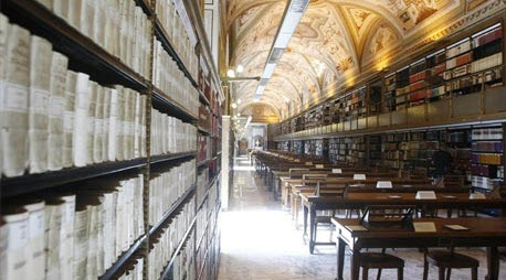
RFID Technology For Books Tracking in Libraries RFID Technology For Books Tracking in Libraries
Searching
and arrangement of misplaced books is a difficult task often carried
out by the library personnel. Many a times Librarians busily search the
improperly placed books or books wrongly placed by the library users and
students in the library of a school, office or college. And often find
this task very difficult. To overcome this problem, an RFID based
intelligent book tracking system has been developed for monitoring the
books in the library through wireless communication between the RFID
reader and the books. This system consists of RFID tag and RFID reader
to detect the information about the books placed in the library.
RFID Technology for Intelligent Tollgate System
The
proposed system performs the following actions such as detecting,
billing and accounting for vehicles as they pass through a toll gate
within the frequency range between 30 kHz and 2.5GHz. In this system, an
RFID tag is programmed with the vehicle owner’s information in the form
with an EPC (electronic product code) that can ensures to read the data
at certain distances and detects the vehicle in order to enhances a
transaction.
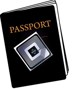
RFID Technology for Authenication of Passport Details RFID Technology for Authenication of Passport Details
A Passport system can become intelligent enough by the implementation of RFID technology
to it. In this system, passport service issues RFID tag to eligible
citizen, which contains passport details like name, address,
nationality, passport number, and other relevant data. During the time
of authentication, the RFID card reader reads that information and
compares it with the data stored in the passport database. If it finds
to be matched, then it will allow for further precedence,otherwise it
alerts the authorities as fake details.
3 Ways to Automatic Plan Irrigation System using Microcontroller
irrigation is defined as artificial application of water to land or soil.
Irrigation process can be used for the cultivation of agricultural
crops during the span of inadequate rainfall and for maintaining
landscapes. An automatic irrigation system does the operation of a
system without requiring manual involvement of persons. Every irrigation
system such as drip, sprinkler and surface gets automated with the help
of electronic appliances and detectors such as computer, timers, sensors and other mechanical devices.
Automatic irrigation system
An
automatic irrigation system does the work quite efficiently and with a
positive impact on the place where it is installed. Once it is installed
in the agricultural field, the water distribution to crops and
nurseries becomes easy and doesn’t require any human support to perform
the operations permanently. Sometimes automatic irrigation can also be
performed by using mechanical appliances such as clay pots or bottle
irrigation system. It’s very hard to implement irrigation systems
because they are very expensive and complex in their design. By taking
some basic points into considerations from experts’ support, we have
implemented some projects on automatic irrigation system by using
different technologies.
In this
article, we are describing about three types of irrigation systems that
work automatically and each system is an advancement of the previous one
as we go from first system to the next, and so on.
1. Automatic Irrigation System on Sensing Soil Moisture Content
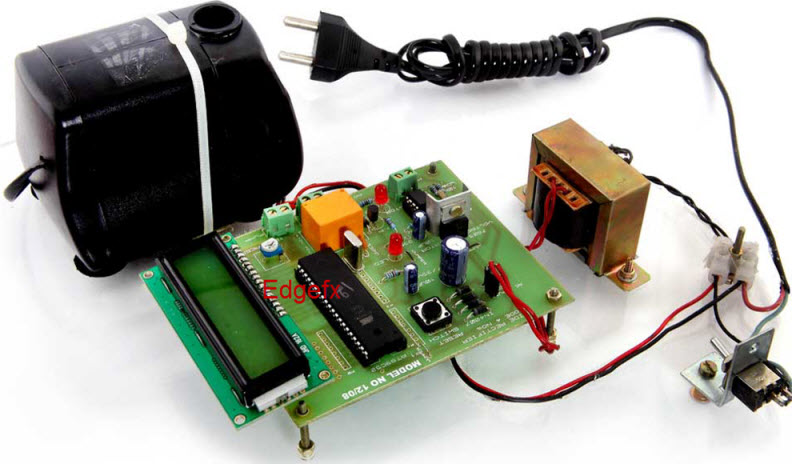
Automatic Irrigation System Circuit by www.edgefxkits.com
The
automatic irrigation system on sensing soil moisture project is
intended for the development of an irrigation system that switches
submersible pumps on or off by using relays to perform this action on
sensing the moisture content of the soil. The main advantage of using
this irrigation system is to reduce human interference and ensure proper
irrigation.
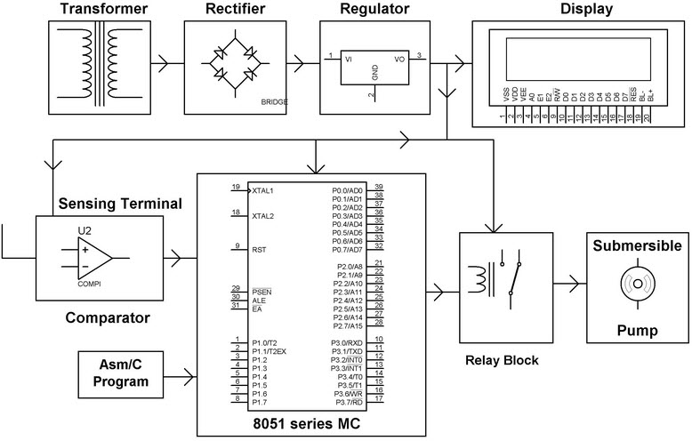
The Microcontroller acts
as a major block of the entire project, and a power supply block is
used for supplying power of 5V to the whole circuit with the help of a
transformer, a bridge rectifier circuit and a voltage regulator. The 8051 microcontroller is programmed
in such a way that it receives the input signal from the sensing
material which consists of a comparator to know the varying conditions
of the moisture in the soil. The OP-AMP which is used as comparator acts
as an interface between the sensing material and the microcontroller
for transferring the moisture conditions of the soil, viz.wetness,
dryness, etc.
Block Diagram of Soil Moisture Content Based Irrigation
Once
the microcontroller gets the data from the sensing material – it
compares the data as programmed in a way, which generates output signals
and activates the relays for operating the submersible pump. The
sensing arrangement is done with the help of two stiff metallic rods
that are inserted into the agricultural field at some distance. The
required connections from these metallic rods are interfaced to the
control unit for controlling the operations of the pump according to the
soil moisture content.
This automatic irrigation system can be further enhanced by using advanced technology that consumes solar energy from solar panels.
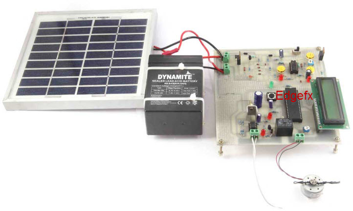
2. Solar Powered Auto Irrigation System
Solar Powered Auto Irrigation System Circuit by www.edgefxkits.com
In
the above figure, the power from utilities is required to operate the
system. As an extension to the above discussed system, this system uses
solar panels to power the circuit. In agricultural field, the proper
usage of automatic irrigation method is very vital due to some
shortcomings of the real world like scarcity of land reservoir water and
scarcity of rainfall. The water level (the ground water table) is
getting reduced due to continuous extraction of water from the ground
and thus gradually resulting in water scarcity in the agricultural zones
slowly turning them into barren lands.
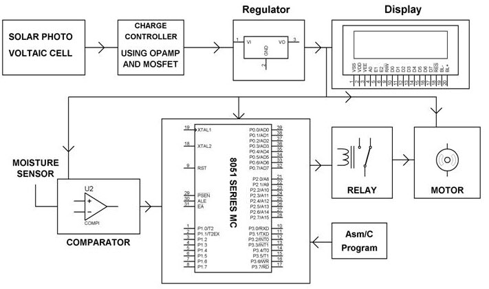
In
the above irrigation system, solar energy generated from the solar
panels is used for operating the irrigation pump. The circuit comprises
moisture sensors built by using OP-AMP IC. The OP-AMP is used as comparators. Two stiff copper wires are inserted into the soil to know whether soil is wet or dry. A charge controller circuit is used to charge the photovoltaic cells for supplying the solar energy to the whole circuit.
Solar Powered Auto Irrigation System Blockdiagram
A
moisture sensor is used for sensing the soil condition – to know
whether the soil is wet or dry, and the input signals are then sent to
the 8051 microcontroller, which controls the whole circuit. The microcontroller is programmed by using KEIL software. Whenever the soil condition is ‘dry’, the microcontroller sends commands to the relay driver and the motor gets switched on and supplies water to the field. And, if the soil gets wet, the motor gets switched off.
The
signals that are sent from the sensors to the microcontroller through
the output of the comparator operate under the control of a software
program which is stored in the ROM of the microcontroller. The LCD
displays the condition of the pump (on or off) interfaced to the
microcontroller.
This automatic irrigation system can be further enhanced by using GSM technology to gain control over the switching operation of the motor.
3. GSM Based Automatic Irrigation System
Nowadays
farmers are struggling hard in the agricultural fields round the clock.
They do their field work in the morning section and irrigate their land
during night time with intermittent intervals. The task of irrigating
fields is becoming quite difficult for the farmers due to lack of
regularity in their work and negligence on their part because sometimes
they switch on the motor and then forget to switch off, which may lead
to wastage of water. Similarly, they even forget to switch on the
irrigation system, which again leads to damage to the crops. To overcome
this problem, we have implemented a new technique by using GSM technology, which is explained below.
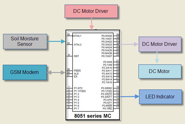
GSM Based Automatic Irrigation System
The
GSM Based automatic irrigation system is a project in which we get
update status of the operation carried out in the agricultural fields
via SMS with the help of a GSM modem. We can also add other systems such
as LCD displays, web cam and other smart controlled devices. In this project, we are using LEDs for indication purpose.
In
this project, we are using soil moisture sensor which is used to sense
the moisture level in the – to know whether it is dry or wet. The
moisture sensor is interfaced with the microcontroller. The input data
signals from the moisture sensor are sent to the microcontroller and
based on that it activates the DC Motor
and switches the motor on with the help of a motor driver. After the
soil gets wet, the Motor gets switched off automatically. The status of
the agricultural fields can be known from the indication of the Light Emitting Diode (LED)
or through the message sent to the GSM modem placed at the field.
Simultaneously it is possible to send messages through a mobile to kit
through the GSM modem. Thus, the irrigation motor can be controlled by
using a mobile and a GSM modem.
This pH Theory Guide focuses on giving a clear and practical
description of how to measure pH in the laboratory and field
environment. A lot of tips and hints are given for the important points
and the whole measurement description is later backed up by the
theoretical description of acidity and alkalinity measurements.
Attention is also given to the different kinds of pH electrodes
available and the selection criteria for choosing the right electrode for a specific sample.
Table of Content:
Introduction to pH.
Electrode selection and handling
Troubleshooting guide for pH measurements
Comprehensive pH theory
1. Introduction to pH
Why
do we classify an everyday liquid like vinegar as being acidic? The
reason for this is that vinegar contains an excess of hydronium ions (H3O+) and this excess of hydronium ions in a solution makes it acidic. An excess of hydroxyl ions (OH–)
on the other hand makes something basic or alkaline. In pure water the
hydroniumn ions are all neutralized by hydroxyl ions and this solution
is what we call at a neutral pH value.
H3O+ + OH– ↔ 2 H2O
Figure 1.
The
reaction of an acid and a base forms water. If the molecules of a
substance release hydrogen ions or protons through dissociation we call
this substance an acid and the solution becomes acidic. Some of the most
well-known acids are hydrochloric acid, sulfuric acid and acetic acid
or vinegar. The dissociation of vinegar is shown below:
CH3COOH + H2O ↔ CH3COO– + H3O+
Figure 2. Dissociation of acetic acid.
Not
every acid is equally strong. Exactly how acidic something is, is
determined by the total number of hydrogen ions in the solution. The pH
value is then defined as the negative logarithm of the hydrogen ion
concentration. (To be precise, it is determined by the activity of the
hydrogen ions. See chapter 4.2 for more information on the activity of
hydrogen ions).
pH = –log [H3O+]
Figure 3. The formula for calculating the pH value from the concentration of hydronium ions.
The
quantitative difference between acidic and alkaline substances can be
determined by performing pH value measurements. A few examples of pH
values of everyday substances and chemicals are given in figure 4:
1.1. Acidic or alkaline 1.2. Why are pH values measured? 1.3. The tools for pH measurements a) The pH electrode b) Reference electrodes c) Combination electrodes 1.4. Practical guide to correct pH measurements a) Sample preparation b) Calibration c) pH Electrode d) Expected measurement accuracy 1.5 Step-by-step guide to pH measurements
2. Electrode selection and handling
For optimal pH measurements, the correct electrode must first be selected.
The most important sample criteria to be considered are: chemical
composition, homogeneity, temperature, pH range and container size
(length and width restrictions). The choice becomes particularly
important for non-aqueous, low conductivity, protein-rich and viscous
samples where general purpose glass electrodes are subject to various
sources of error.
The response time and accuracy of an electrode
is dependent on a number of factors. Measurements at extreme pH values
and temperatures, or low conductivity may take longer than those of
aqueous solutions at room temperature with a neutral pH.
The
significance of the different types of samples is explained below by
taking the different electrode characteristics as a starting point.
Again, mainly combined pH electrodes are discussed in this chapter.
Figure 14. Electrode with ceramic junction.
a) Ceramic junctions The opening that the reference part of a pH electrode contains to maintain the contact with the sample can have several different forms. These forms have evolved through time because of the different demands put on the electrodes when measuring diverse samples. The ‘standard’ junction is the simplest one and is known as a ceramic junction. It consists of a porous piece of ceramic which is pushed through the glass shaft of the electrode. This porous ceramic material then allows the electrolyte to slowly flow out of the electrode, but stops it from streaming out freely. This kind of junction is very suitable for standard measurements in aqueous solutions; the METTLER TOLEDO InLab®Routine Pro is an example of such an electrode. A schematic drawing of the principle of this junction is shown below in figure 14.
.. get more in the pH Theory Guide ....
2.1. Different kinds of junctions a) Ceramic junctions b) Sleeve junctions / ground glass junctions c) Open junctions 2.2. Reference systems and electrolytes 2.3. Types of membrane glass and membrane shapes 2.4. pH electrodes for specific applications Easy samples Dirty samples Emulsions Semi-solid or solid samples Flat samples and very small samples Small samples and difficult sample containers InLab®Power (Pro) 2.5. Electrode maintenance 2.6. Electrode storage Short term storage Long term storage Temperature sensors 2.7. Electrode cleaning Blockage with silver sulfide (Ag2S) Blockage with silver chloride (AgCl) Blockage with proteins Other junction blockages 2.8. Electrode regeneration & lifetime 2.9. Additional information
3.Troubleshooting guide for pH measurements
Problems
which arise during pH measurements can have different sources; from the
meter, cable and electrode, down to the buffer solutions, measuring
temperature and sample (application). Special note should be taken of
the symptoms of the problem as these are useful for locating the origin
of the fault. The following table gives an overview of symptoms and
causes:
Readings too high/too low or off-scale readings “---”
Check meter, cable, electrode, calibration procedure and sample temperature
Value does not change
Check meter, cable and electrode
Slow response time
Check electrode and sample/application
High offset after calibration
Check electrode, buffer solutions and calibration procedure
Low slope after calibration
Check electrode, buffer solutions and calibration procedure
Calibration error
Check meter, cable, electrode, buffer solutions and calibration procedure
Drifting measurement values
Check electrode and sample/application
pH Electrode Troubleshooting Guide
4. Comprehensive pH theory
In
the previous sections the practical aspects of pH measurements were
discussed. This chapter will principally deal with the theoretical
background to pH measurements and is intended for readers wishing to
acquire a more fundamental understanding of pH theory.
First
the basic pH theory is developed, then we will have a look at the sensor
theory and at the end some special topics will be dealt with.
4.1. Definitionof the pH value
According to Sørenson the pH is defined as the negative logarithm of the H3O+ ion concentration:
pH = –log [H3O+]
From the equation we can see that if the H3O+
ion concentration changes by a decade, the pH value changes by one
unit. This nicely illustrates how important it is to be able to measure
even small changes in the pH value of a sample. Often, the pH theory is described with H+
ions in connection with pH values, although the correct ion to refer to
is the hydronium (or as it is officially known according to IUPAC:
oxonium) ion (H3O+):
H+ + H2O ↔ H3O+
Not only acids and bases show dissociation behavior to form hydronium
ions or hydroxide ions, but pure water also dissociates to form
hydronium and hydroxide ions:
4.1. Definition of the pH value 4.2. Correlation of concentration and activity 4.3. Buffer solutions Buffer capacity (ß) Dilution value (ΔpH) Temperature effect (ΔpH/ΔT) 4.4. The measurement chain in the pH measurement setup pH electrode Reference electrode 4.5. Calibration/adjustment of the pH measurement setup 4.6. The influence of temperature on pH measurements Temperature dependence of the electrode Isothermal intersection Further temperature phenomena Temperature dependence of the measured sample 4.7. Phenomena in the case of special measuring solutions Alkaline error Acidic error Reactions with the reference electrolyte Organic media
In the 1980’s, two ophthalmologists Aran
Safir and Dr Leonard Flom proposed that no two irises are similar, even
in twins, thus making them good biometric authentication units. This
concept was based on the clinical experience with which they viewed the
individual features of irises such as crypts, coronas, colors, pits,
contraction furrows, striations, freckles and rifts. After researching
and documenting the use of irises as a means of recognizing people, they
were awarded a copyright in 1987. In 1990, Dr. John Daugman created the
algorithm to implement iris technology. These algorithms utilize the
methods of some mathematical calculations and pattern recognition of
iris.
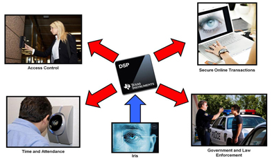
Nowadays access control systems
are becoming more essential. The number of systems that have been
compromised is ever increasing and one area where security can be
enhanced is authentication. A biometric and Iris technology afford
secure methods of identification and authentication. Iris Technology is
used in many areas like airport security, ATMs, physical access security and information security.
Iris Technology
Iris Recognition Technology
Iris-recognition
is a biometric technology which deals with the recognition based on the
human Iris. Iris-recognition technology is considered to be the most
accurate biometric technology available today. The Iris is an inner
organ of the body which is observable, or it is the area of the eye
wherein the colored or pigmented circle, which is generally blue or
brown, rings the dark purple area of the eye.
Iris Recognition System
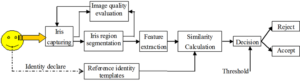
Iris
feature is an easy option of a person to prove his identity, which is
based on his biometrics at any time and at any place. Iris recognition
is an important identifying approach in many departments such as
finance, navigation, etc. This system’s main features include Iris
capturing, Image quality evaluation, Iris region segmentation, feature
extraction, similarity calculation and decision making. Every part is
very important in this recognition system for correct recognition of a
person’s identity.
Iris Recognition System
There
are plenty of features in iris areas of human eye’s image. The iris is a
small and black object, and capturing of iris image is not an easy
work. To capture iris, we have to maintain some distance about 4 to 13
cm under a good-lighting environment. For many evident image recognition
systems, infrared light source is better
such as face-recognition system. It can perform a better light for
enhancing image contrast, and furthermore, infrared light is harmless to
eyes. In order to capture the best iris image, a person’s cooperation
is necessary, and also the captured image supports iris recognition. A
good cooperation can reduce the capacity of iris pre- processing and
make iris recognition a real-time character. Therefore, under
incorporate conditions so many researchers initiate to study the theory
of imperfect iris recognition.
The
process and working of iris recognition takes place like this: a picture
of the iris is captured by a camera attached to a wall within a
distance of 4 to 13 inches, and then the image is processed by a special
type of software that separates the main iris patterns from the inner
and outer boundaries of the iris. By using Dr. Daugman’s algorithm, the
patterns of the iris from the processed image are encoded into a 512-bit
code called as the iris code. The encoded code is encrypted as soon as
it is calculated to avoid from theft. The calculated iris code is then
compared to the codes that are stored in the database for matching and
pattern recognition. The speed of searching the database can be up
to10,000 codes/sec. Therefore, within a few seconds, a person can be
recognized without any particular user action.
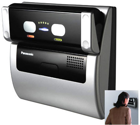
Iris Scanner
Iris
Scanners are becoming more and more common in security applications
nowadays as no two people’s eyes share similar iris patterns, and thus
they are less matchable. Iris scanning has become very advanced, but at
the heart of the system is a CCD digital camera. This camera uses both
infrared and visible light to take a clear picture of a person’s iris.
When a person’s pupil is black – with near IR light – to isolate the
iris and pupil is easier for the computer. When a person looks into an
iris scanner, the digital camera automatically focuses audible feedback
from the system to make the person’s position correctly. When the camera
takes a picture from 3 to 10 inches distance, the computer locates the
center of the pupil, edge of the iris and pupil, the eye lashes and
eyelids. It then calculates the patterns of the iris and translates them
into a code.
Iris ScannerThe
iris is a visible but protected structure, and it doesn’t change over a
time usually. Most of the time a person’s eyes also stay unchanged even
after eye surgery and even blind people can use these scanners as long
as their eyes have irises. Typically contact lenses and eye glasses do
not cause inaccurate readings.
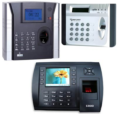
Biometric System
Nowadays a biometric access control system
plays an essential role, and this system has realized the value of
biometrics for two reasons: one is to identify, and the other to verify.
The benefit of using biometric authentication is that it cannot be
forgotten or lost as the person needs to be available during the point of identification process. Essentially, this system is more capable and reliable than the token-based and traditional knowledge-based techniques.
Biometric Systems
A Biometric system is a technological system that uses information
about a person to identify that person. In order to work effectively,
these systems depend on particular data based on some exclusive
biological traits and qualities. This system has its major hub in
distributions of electronic security system such as access-control
system, time-attendance system based on fingerprints, facial-recognition
attendance system, smartcard and proximity-based products, etc. The
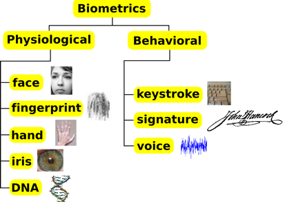
characteristic of biometrics can be classified into two types, which is
represented in the following figure.
Physiological Biometrics:
These types of biometric systems are related to the shape of the body
and these systems include face recognition, iris recognition, fingerprint recognition, hand recognition and DNA recognition.
Behavioral Biometrics:
These types of biometric systems are related to the behavior of a
person and this type of biometrics includes voice, keystroke and
signature recognition.
Characteristic of Biometrics
Advantages
Due to exclusivity of iris patterns provide improved accuracy.
This type of recognition cannot be forged or modified
Being the internal organ of the eye, Iris is highly protected
Offers better scalability and speed
Disadvantages
Iris scanning being a new technology is mismatched with most of the electronic gadgets that are available.
Iris scanning is difficult to perform without proper cooperation of the person.
Iris technology is susceptible to poor image quality with other photographic biometric technologies.
Equipment’s used for scanning are very difficult to handle.
Applications
The largest application of the iris recognition is in the aviation industry.
The world’s largest airports like Heath row Airport of London employ iris recognition.
In Unite Arab Emirates millions of iris code comparisons are done each day at all the air, land and seaports.
The
other applications of iris recognition system include Information
security, security in online business, security in government
applications, usage in security agencies to keep a record of criminals
by police departments.
Thus,
Iris technology has proved to be a very useful and adaptable security
measure. It is an accurate and quick way of identifying an individual
with no chance of human error. Iris recognition is widely used in many
applications where security is necessary. In the future it will prove to
be a widely used security measure.
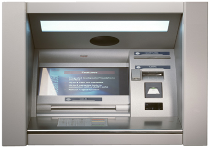
The automatic teller machine (ATM) is an automatic banking machine (ABM)
which allows customer to complete basic transactions without any help
of bank representatives. There are two types of automatic teller
machines (ATMs). The basic one allows the customer to only draw cash and
receive a report of the account balance. Another one is a more complex
machine which accepts the deposit, provides credit card payment
facilities and reports account information.
It is an electronic device which is used
by only bank customers to process account transactions. The users
access their account through special type of plastic card that is
encoded with user information on a magnetic strip. The strip contains an
identification code that is transmitted to the bank’s central computer
by modem. The users insert the card into ATMs to access the account and
process their account transactions. The automatic teller machine was
invented by john shepherd-Barron in year of 1960.
Automatic Teller Machine
Automatic Telling Machine Block Diagram:
The Automatic telling machine consists of mainly two input devices and four output devices that are; Input Devices:
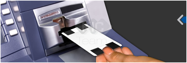
The
card reader is an input device that reads data from a card .The card
reader is part of the identification of your particular account number
and the magnetic strip on the back side of the ATM card is used for
connection with the card reader. The card is swiped or pressed on the
card reader which captures your account information i.e. the data from
the card is passed on the host processor (server). The host processor
thus uses this data to get the information from the card holders.
Automatic Teller Machine Card Reader
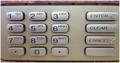
Keypad:
The
card is recognized after the machine asks further details like your
personal identification number, withdrawal and your balance enquiry Each
card has a unique PIN number so that there is little chance for some
else to withdraw money from your account. There are separate laws to
protect the PIN code while sending it to host processor. The PIN number
is mostly sent in encrypted from. The key board contains 48 keys and is
interfaced to the processor.
Automatic Teller Machine keypadOutput Devices:
Speaker:
The speaker provides the audio feedback when the particular key is pressed.
Display Screen:
The
display screen displays the transaction information. Each steps of
withdrawal is shown by the display screen. A CRT screen or LCD screen is
used by most of ATMs. Automatic Teller Machine LCD Display
Receipt Printer:
The
receipt printer print all the details recording your withdrawal, date
and time and the amount of withdrawn and also shows balance of your
account in the receipt.
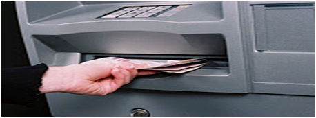
Cash Dispenser:
The cash dispenser is a heart of the ATM. This is a central system
of the ATM machine from where the required money is obtained. From this
portion the user can collect the money. The duty of the cash dispenser
is to count each bill and give the required amount. If in some cases the
money is folded, it will be moved another section and becomes the
reject bit. All these actions are carried out by high precision sensors.
A complete record of each transaction is kept by the ATM machine with
help of an RTC device.
Automatic Teller Machine Cash Dispenser
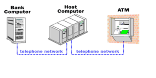
ATM Networking:
The
internet service provider (ISP) also plays an important role in the
ATMs. This provides communication between ATM and host processors. When
the transaction is made, the details are input by the card holder. This
information is passed on to the host processor by the ATM machine. The
host processor checks these details with authorized bank. If the details
are matched, the host processor sends the approval code to the ATM
machine so that the cash can be transferred.
Automatic Teller Machine Networking
2 Types of ATM Machines
Most of the host processors can support either leased line or dial up machines
Leased line ATM machines
Dial up ATM machines
Leased Line ATM Machines:
The
leased line machines connect direct to the host processor through a
four wire point to point dedicated telephone line. These types of
machines are preferred in place. The operating cost of these machines is
very high.
Dial Up ATM Machines:
The
dial up ATMs connects to the host processor through a normal phone line
using a modem. These require a normal connections their and their
initial installation cost is very less. The operating cost of these
machines is low compared with leased line machines.
ATM Security:
The
ATM card is secured with PIN number which is kept secret. There is no
way to get the PIN number from your card. It is encrypted by the strong
software like Triple data Encryption Slandered.
Automatic Teller Machine Working Principle:
Automatic Teller Machine Circuit Diagram
The
Automatic teller machine is simply a data terminal with two input and
four output devices. These devices are interfaced to the processor. The
processor is heart of the ATM machine. All the ATM machines working
around the world are based on centralized database system.
The ATM has to connect and communicate with the host processor
(server). The host processor is communicating with the internet service
provider (ISP). It is the gateway through all the ATM networks
available to the card holder.
Automatic Teller Machine Architecture
When
a card holder wants does an ATM transaction, user provides necessary
information through card reader and keypad. The ATM forwards this
information to the host processor. The host processor enters the
transaction request to the cardholder bank. If the card holder requests
the cash, the host processor takes the cash from the card holder
account. Once the funds are transferred from the customer account to
host processor bank account, the processor sends approval code to the
ATM and the authorized machine to dispense the cash. This is the way to
get the amount on ATMs. The ATM network is fully based on centralized
database environment. This will make life easer and secured the cash.
Advantages of Automatic Teller Machine:
The ATM provides 24 hours service
The ATM provides privacy in banking communications
The ATMs reduce the work load banks staff
The ATM may give customer new currency notes
The ATMs are convenient to banks customers
The ATM is very beneficial for travelers
The ATM provide services without any error
Features of Automatic Teller Machine:
Transfer funds between linked bank accounts
Receive account balance
Prints recent transactions list
Change your pin
Deposit your cash
Prepaid mobile recharge
Bill payments
Cash withdrawal
Perform a range of feature in your foreign language.